
Manufacturability Considerations for Flex PCBs
Despite the fact that flex circuits are more flexible than traditional rigid PCBs, they require just as much attention to design for manufacturability. In fact, the complexities of flex circuit design can sometimes make them more difficult to fabricate than rigid PCBs. This is because they require additional layers, different materials, and unique manufacturing processes.
In order to minimize these issues, first-time flex designers must review basic DFM considerations for these kinds of boards. These include:
Conductors and routing: Ensure that the trace contour follows the outline contour of the PCB, which is important for proper manufacturing yield. The contour should also be round instead of angled to avoid mechanical stress during bending. This is especially true for traces on multilayer flex boards. Also, stagger the traces across the board to eliminate stress points that may cause breakage during bending. It’s also a good idea to cross-hatch ground planes on both sides of the signal layers, as this can improve impedance control.
Bend radius: Ensure the bending radius of the flex circuit pcb is appropriate for the operating environment. This will not only increase the life of the flex circuit but will also reduce the risk of damage during bending. It is a good idea to use a computer-aided engineering (CAD) software that has the ability to automatically generate bend radius calculations for traces and pads in your design.
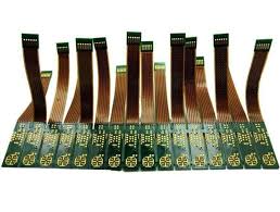
Design For Manufacturability Considerations for Flex PCBs
The thickness of the flex circuit is another factor that influences its flexibility. Thicker boards are more rigid, while thinner ones are more flexible. Therefore, the optimum thickness is somewhere in between.
Stiffeners: Including stiffeners in your flex PCB will help support the circuit during bending and protect components and connectors that are attached to the flex circuit. A stiffener can be made of a variety of materials, such as FR4, polyimide, stainless steel, or even aluminum. The stiffener should be placed in the area of the flex circuit where additional support is needed or to prevent the flex circuit from moving during bending.
Hole to bend distance: When a hole is placed too close to the flex section of the board, it will create stress on the copper traces and can cause them to break during bending. This is why it’s important to consult with your CM’s engineers before finalizing the flex PCB design.
The best way to ensure that your flex circuit will perform well is by working with a reliable and experienced manufacturer. Choose a turnkey PCB manufacturer who can offer advanced assembly and testing services. This will eliminate multiple vendor miscommunication and ensure that all of the necessary steps are taken to prepare the flex circuit for manufacturing. The manufacturer should also be capable of removing any moisture before sending the board to be soldered. It is also a good idea to visit the manufacturer’s facilities to see their capabilities firsthand. This will also allow you to ask questions and gain a better understanding of how your flex circuit will be handled during the production process.


;)